News
Thermal Infrared Sensor Design
Thermal Infrared Sensor Design - Considerations for Counter-UAS Defense
Executive Summary
The use of small, low‑cost drones has rapidly expanded across military and public safety environments, creating an urgent need for effective Counter-Unmanned Aerial System (C-UAS) solutions. This paper outlines how EO/IR sensors form the backbone of the C-UAS kill chain, and compares the trade‑offs between lower‑cost imaging systems and high‑performance, multi‑sensor architectures. It highlights the challenges of long‑range detection, where drones may appear as only a few pixels, and performance is constrained by the Signal-to-Noise Ratio (SNR). The paper also emphasizes the limitations of both classical MTI and AI‑based object detection at the edge of visibility. Finally, it underscores the essential role of advanced Image Signal Processing (ISP) in improving SNR, stabilizing low‑contrast targets, and extending effective detection and tracking range.
Introduction and Background
The drone threat is emerging across tactical and public safety scenarios. The proliferation of small, inexpensive, and maneuverable drones is a great challenge for both military planners and for the protection of public, commercial, and industrial vulnerabilities. It is not hyperbole to state that there is an arms race between offensive drones and C-UAS solutions.
Electro-optical (EO) and thermal infrared (IR) imaging have become core technologies for detecting and tracking drones. To perform a cost/benefit analysis, developers need to understand the trade space of C-UAS systems, including detection range limitations, radar system capabilities, image signal processing, embedded processors, and Artificial Intelligence (AI) models. Although each air defense system is developed against a specific set of air threats, their kill-chains all typically consist of three complex sub-systems: Sensor Systems, Command Control System, and Defeat Systems.
The Russian-Ukrainian war has become a crucible for UAS innovation, accelerating the capabilities and tactics of drones. Though defeat systems like radio jamming, GPS signal jamming, and kinetic effectors are deployed along battle lines, these systems are expensive and have limited deployment in public safety applications.
EO/IR Imaging Systems for Drone Detection
Cost-effective electro-optical (EO) sensors offer high resolution and appropriate focal length lenses. Passive infrared (IR) sensors are sensitive to thermal photon emissions instead of visible light, making IR ideal for 24/7 operations. EO cameras have higher angular resolution, which directly translates to pixels on target: this is a critical system parameter for early drone detection. However, the SNR of the EO pixels on a small drone is often low due to limited contrast against a sky background. IR cameras can often detect drone motion represented by as small as a 2x2 pixel cluster, given the sky’s cold background. In addition, classification cues, including shape, motion patterns, and thermal signatures, help IR distinguish drones from birds, aircraft, and clutter to minimize false positives, which often diminish the effectiveness of imaging systems.
C-UAS Solution Design Considerations
C-UAS detection systems fall into two separate cost and performance categories: lower cost and high performance. Lower-cost, imaging-only detection systems with <1000-meter drone detection distance integrate EO and Longwave IR (LWIR) uncooled sensors with fixed focal length lenses and cost between $50K and $150K. These systems are typically limited to a fixed field of view (FOV) or scanning 90 to 180 degrees horizontally, which is useful for perimeter monitoring. Advanced, high-performance, multi-sensor detection systems with >1000-meter range incorporate EO and cooled Midwave IR (MWIR) cameras with continuous zoom (CZ) optics and radar. These systems cost between $150K and $1M and can be configured to provide a full 360-degree FOV for maximum situational awareness.
Lower-cost C-UAS solutions typically include the following:
- EO and uncooled LWIR infrared cameras with either long focal length or zoom optics
- Fixed or pan and tilt mounting
- Embedded computer for object detection and tracking
- Defeat system, typically RF jamming
High-performance C-UAS solutions typically include the following:
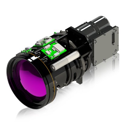
- EO and cooled MWIR cameras with long-range, CZ optics
- Pan and tilt or stabilized gimbal on stationary or mobile platforms with extendable masts
- Wide-area, high-resolution radar units used for camera slew to cue
- Acoustic sensors
- Server or PC-based
- Defeat systems – all types, including kinetic
When selecting an EO camera, there are many specifications to consider: color versus monochrome, resolutions up to 200MP, and rolling versus global shutter. There are system-level trades for pixel rate, edge embedded signal processing, bit rate, sensitivity, and lens selection. EO systems provide 2x to 8x more resolution and pixels on target than an IR camera, but the detection range performance is a function of SNR.
When selecting an uncooled LWIR thermal camera, most systems specify a 640x512-resolution sensor with a thermal sensitivity of less than or equal to (≤)20 millikelvins (mK) and fast optics specified by a f-number between ƒ0.9 and ƒ1.4. This translates to a lens aperture (diameter) nearly equal to the focal length, but there is a practical size limit to longer focal lengths and zoom ranges. There is also a cost crossover point from uncooled LWIR to cooled MWIR at focal lengths greater than approximately 250 mm.
Today’s MWIR systems incorporate compact closed-cycle coolers with Mean Time to Failure (MTTF) of up to 27,000 hours that operate at low power. Because this sensor technology is much more sensitive than uncooled LWIR, optics as slow as ƒ5.5 can be used, enabling focal lengths more than 1000 mm while keeping the lens assembly to a manageable size and cost. Today’s cooled MWIR sensors have 8-micron pixels with resolutions up to 1280x1024 and sensitivity of 30 mk.
EO/IR Moving Target Indication at Low SNR
EO/IR C-UAS systems employ Moving Target Indication (MTI) algorithms as a first stage, using techniques including frame differencing or temporal differencing and background subtraction. Near the detection limit, noise is indistinguishable from motion, and pixel-level noise fluctuations can look like small moving objects from frame-to-frame, especially under high gain or low light. Background movements, including moving foliage, clouds, water, heat shimmer, and shadows, generate “false motion.” Increasing detection thresholds keeps false positives manageable but can disproportionately suppress true detections at the edge of visibility.
MTI detections are subject to significant false positives. It is good practice to accumulate MTI detections and quantify detections in a hierarchy. The user can then determine how sensitive the system should be relative to early detections and acceptable false positives. The camera produces many noisy “blobs” or micro-tracks that need to be confirmed. In operation, MTI at the limit of detection often acts as a candidate generator for an AI object detector and target tracker.
Target Detection and Tracking Using EO/IR Object Detectors
Deep learning, AI-based object detectors are widely used for drone detection in EO/IR video systems and can follow the same ontology as the human perception classes of detection, recognition, and identification. They incorporate multi-scale feature extraction:
- Detection (>10x10 Pixels): Generalized classifiers (drone vs. bird vs. plane) and localization (bounding box) for small to large targets based on limited training data
- Recognition (~20x10 Pixels): Fine-grained classifiers for target classes such as quadcopter, fixed wing drone and airborne ISR aircraft
- Identification (~30x20 Pixels): Fine-grained classifiers based on extensive high-resolution training data of application-specific classes such as Shahed, quadcopter make and model, and fixed wing loitering targets
Limits of Detection for EO/IR
For drones at long range, EO/IR performance is often SNR- and resolution-limited, forcing the system to operate near the limit of detection. For a small quadcopter or fixed-wing drone, the angular size at long range may be only a few pixels or even sub-pixel. At that point, the drone’s apparent size is comparable to or smaller than the point spread function (PSF) of the optics. Atmospheric effects, including scattering, haze, and turbulence, can further reduce contrast and introduce random blur. Limit-of-detection conditions often correspond to:
- SNR: Low SNR (1–3) at the pixel or small-patch level
- Area: Very small apparent area (<20 pixels)
- Background: Intermittent visibility as the drone crosses complex backgrounds, e.g., trees, buildings, clouds, etc.
Most object detectors degrade severely when the object is below approximately 10×10 pixels. At 3×3 or up to 5×5 pixels, the network has very little detail, shape cues are limited, texture is nonexistent, and only gross motion/contrast remains. If network training does not include very small, noisy targets, the detector will miss targets or produce unstable outputs. Detectors trained using clean daytime imagery, specific backgrounds, and strong contrast targets may be especially challenged or fail in low-light or night conditions, haze or humidity, and background variations, e.g., desert vs. urban vs. maritime.
At the limit of detection, any mismatch between training and deployment distributions is magnified. Training data labeling and annotation practices are very important for very small targets. Manual annotation can be prone to error. Bounding boxes may not line up with the true target and may miss targets entirely at the extreme range. This introduces label noise that can confuse the detector and limit its ability to learn fine distinctions at low SNR.
Furthermore, training data rarely includes examples of small, strongly blurred drones; most CNN networks are biased toward sharp or moderately blurred targets. Blur and camera motion are major constraints on EO/IR drone detection, especially at long range or on moving platforms. Tracking-by-detection pipelines rely on detections that are consistent in position and size. Blur causes jitter and size variability, breaking data association. Classical trackers, e.g., KLT features or template matching, struggle when the internal appearance of the template changes drastically due to blur direction and magnitude.
To improve performance, development teams can use data augmentation, including scaling, noise injection, blur, and illumination changes. Training on synthetic data enables rendering drone models into realistic backgrounds and negative examples of birds, planes, and clutter. Multi-frame or track-aware detectors can be employed using sequences instead of single frames.
EO/IR Image Signal Processing
ISP for EO/IR camera systems refers to the set of algorithms and hardware functions that convert raw sensor data into usable, high‑quality imagery that supports detection, recognition, identification, measurement, and automated decision‑making. In EO/IR systems, especially thermal IR cameras, raw output from the focal plane array (FPA) is noisy, nonlinear, and uncorrected. ISP transforms this raw data into stable, calibrated, visually optimized imagery in real time. SNR and network performance and reliability depend on the quality of ISP for improving target Detection, Recognition, and Identification (DRI). Teledyne FLIR OEM has developed IR ISP algorithms to improve the SNR and at the limits of detection (~2x1.5 pixels) that increase the range to initiate drone tracking by up to 20%. To learn more, please visit
www.flir.com/oem